|

Crystal Oscillators
The circuit below is a standard oscillator of the Colpitts variety. Similar circuits have been used in many ham radio
homebrew transmitters. This particular circuit should function well at frequencies from 1500 kHz to 8000 kHz. For use on lower
frequencies, the values of C1 and C2 might need to be increased.
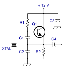
C1: 100 pF ceramic disc or silver mica
C2: 680 pF ceramic disc or silver mica
C3: .01 uF ceramic disc
C4:
.001 uF ceramic disc
Q1: 2N3904
R1: 220 K
R2: 1 K
Beginner's assembly instructions:
If you've never built a circuit from a schematic before, this might be a good one to start with. The diagram below shows
how you can arrange the parts on a prototyping board such as Radio Shack catalog number 276-175. (A prototyping board, also
called a solderless breadboard, contains groups of holes that are electrically connected. Each hole has a little spring/clamp
thingy in it that grabs ahold of the component leads. This is a great way to experiment with circuit designs and learn about
the building process.)
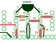
Attach a 10-inch (25 cm) piece of bare wire to the output, then sit a radio next to the circuit and tune to the crystal
frequency. Apply power. If everything is connected correctly and all the components are in working order, you will hear the
carrier (or the silence caused by it) on your receiver. Now all you need to do is add a buffer amp, a modulation stage, a
final RF amp, a harmonic suppression and output matching section, and you've got an AM transmitter. :-)
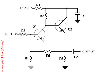
Below is another version of the circuit with a couple of enhancements. The variable capacitor between the crystal and
ground allows you to adjust the frequency slightly. (More capacitance equals lower frequency.) Q2 serves as a buffer amplifier
which stabilizes the circuit and boosts the output power. This circuit was developed independently by another MWA member and
uses very different values for R1, C1 and C2 compared to the first circuit on this page; don't let those differences scare
you.
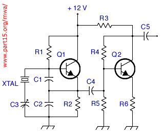
C1, C4, C5: .001 uF
C2: .0033 uF
C3: 20 to 50 pF variable
Q1, Q2: 2N3904
R1: 22 K
R2, R6: 1 K
R3:
18 K
R4: 270 K
R5: 470 K
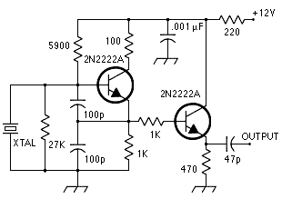
Another common variation of the Colpitts circuit involves adding a resistor parallel to the crystal, as shown below.
What's the advantage? I have no idea. The circuit shown has been tested and works fine at frequencies from 1.5 to 20 MHz.
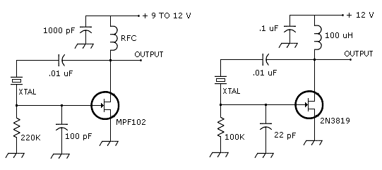
To round out the collection, here's a Pierce oscillator using an FET. The version on the left is from an electronics
textbook. The version on the right is from the "Grenade" shortwave pirate radio transmitter designed by "Radio Animal."
VFO
A VFO (variable frequency oscillator) allows you to operate across a range of frequencies without investing in a lot of
crystals and without the complexity of a PLL circuit. There are 4 keys to building a stable VFO:
1. Use a regulator IC or a zener diode to regulate the voltage going to the oscillator. Voltage fluctuations produce frequency
drift.
2. Build the circuit carefully. Keep component leads short, do your best soldering work, and make sure all the components
are physically secure (no wiggling).
3. Choose your inductor and variable capacitor carefully. Air-core inductors are more stable across a range of temperatures
than iron-core inductors. Air-dielectric variable capacitors are more stable than mica compression and other types.
4. Put a buffer amplifier between the VFO's output and the rest of the transmitter. Failure to do this makes the VFO vulnerable
to being "pulled" by modulation, by changes in antenna loading, etc.
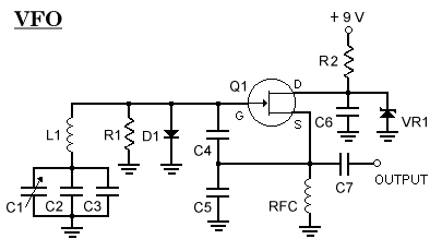
The circuit shown here is a series-tuned Clapp oscillator. Unlike the parallel LC tanks seen in many oscillators, this
one has the LC components in series. Similar VFOs have been used successfully in many ham radio transmitters and receivers.
Parts:
C1: 4 to 20 pF, air-dielectric variable capacitor
(such as Antique Electronic
Supply catalog number C-VT20)
C2: 100 pF polystyrene
C3: 82 pF polystyrene (for approx. 1640-1700 kHz tuning range)
or 100 pF polystyrene (for 1570-1630 kHz tuning range)
C4, C5: 1000 pF
C6: .01
uF ceramic disk
C7: 50 pF polystyrene
D1: 1N914
L1: 47 uH inductor
Q1: MPF102
R1: 100 K, 1/4 watt
R2:
470 ohm, 1/4 watt
RFC: 1 millihenry choke
VR1: any 8 or 8.2 volt, 1/2 watt zener diode (such as NTE 5016A)
With special thanks to the late Doug DeMaw, who taught so much to so many.
PLL.
Buffer Amplifiers
A buffer amp can be inserted between the oscillator and the rest of a transmitter circuit. The buffer not only increases
the power of the signal but also prevents the oscillator frequency from being affected by modulation, changes in antenna loading,
etc.
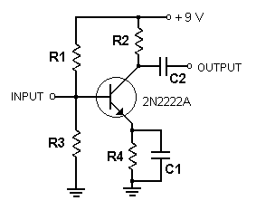
Above is the simplest buffer amp we could dig up. It is designed to work with a 9 volt power supply.
Parts:
C1: .1 uF
C2: .01 uF
R1: 27 K
R2: 22 ohms
R3: 5600
R4: 270
Above is a deluxe buffer amp that uses a pair of bipolar transistors. Some of the resistor values are a little different
depending on whether it is built with 3904's or 2222's.
Parts:
Q1, Q2 2N2222A 2N3904
R1 100
47
R2 1 K
1 K
R3 10 K
10 K
R4 2200
10 K
R5 10 K
22 K
R6 330
330
C1 .1 uF
.1 uF
C2 .01 uF .01
uF
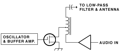
Simple Modulators for Solid-State Transmitters
Simple AM modulators work by varying the amount of power flowing through the transistor which is serving as the RF output
amplifier. By imposing an audio waveform on the power supply, amplitude modulation is achieved.
Rather than giving detailed examples, this page gives simplified schematics, followed by links to circuits that actually
use the various techniques.
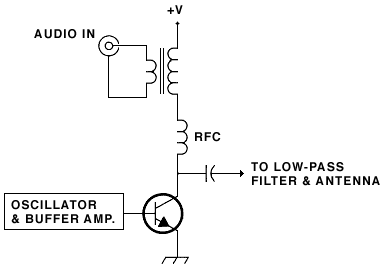
An external audio amp sends its output to the 8-ohm side of an 8-to-1000 ohm (or similar) audio transformer. The other
winding of the transformer is inserted in the power supply going to the final RF amp transistor. The audio transformer must
be rated to handle the level of power going through it; an inadequate transformer will produce a bad-sounding signal. In some
cases it takes a lot of searching and experimentation to find the best transformer.
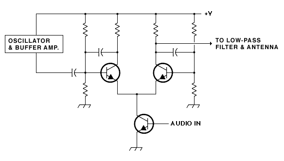
technique #2-A
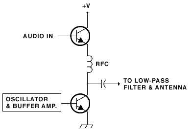
A lightly amplified audio signal is fed to the base of an NPN transistor. This transistor is inserted into the power
supply going to the RF amp transistor. A choke between the two transistors keeps RF out of the power supply and audio circuitry.
The RF choke must be rated to handle the level of current going through it.
technique #2-B
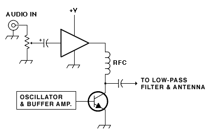
A line-level audio signal is fed to an audio amplifier I.C. The output of this chip is used as a power supply for the
RF amp transistor.
This circuit is physically smaller and lighter than designs that use a modulation transformer. The audio quality is good.
technique #3
The RF output transistor is an FET (often an IRF510 or similar). The FET's source is grounded. The FET's drain is connected
to a transformer, which has the modulation (audio) amp on one side and the RF output taken from the other side.
technique #4
This is the system used in Charles Wenzel's circuit. This design has had many re-incarnations, for example in a proposed
13.5 MHz transmitter circuit. The Wenzel modulator is capable of high quality modulation at levels approaching 100%. For 100
milliwatt transmitters, suitable transistors are 2N4401 or 2N5551.
Finals
Call 'em PA's, finals, or output amps, these are the last chance for the signal to get amplified before it is hurtled
out into the world. Shown here are some partial schematics of finals taken from a wide variety of sources. Unless otherwise
noted the input is on the left side, output on the right.
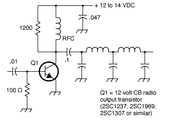
The circuit above will output 1.2 watts with a 13.8 volt power supply. Value of RFC not critical, but must be able to
handle some current, try 15 turns of wire on a toroid core.
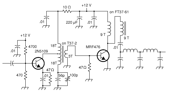
The circuit above will output 4 to 5 watts with an adequate power supply. The design shown is optimized for 7 MHz; the
transformers may need a bit of modification to optimize for other bands. Provide heat-sinks for the transistors.
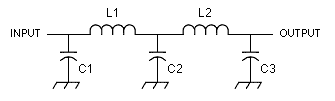
Low-pass filters
"Station WRNY is equipped with the latest device known to the world of radio engineering, called a harmonic suppressor,
the effect of which is the elimination of the signals of WRNY from every frequency except that to which it has been assigned
by the Government, which means, in fan language, that the station may be tuned in on only one setting of the dial." Radio
News magazine, August 1925
A low-pass filter attentuates the energy above a specified cut-off frequency. These filters are used to reduce the intensity
of harmonics so that they don't interefere with other signals. Most of this filters on this page were designed for various
ham radio gear operating in the bands from 1.8 to 14 MHz.
Unless otherwise noted these filters have 50 or 52 ohms input and output impedance. Capacitances are expressed in picofarads,
inductances in microhenries. Most authors recommend using silver-mica capacitors.
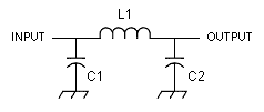
for transmit frequencies
in the range of C1 C2
L1
1500-2000 kHz 1800 1800 30 turns #26 wire on T-50-2 toroid
3500-4500
kHz 680 680 21 turns #22 wire on T-50-2 toroid
5500-7300 kHz
470 470 14 turns #22 wire on T-50-2 toroid
5500-7300 kHz
820 820 2.2
approx.
cutoff freq. C1
C2 C3
L1, L2
1200 kHz .0039 uF .0056 uF .0039
uF 6.8
1800 kHz .0033 uF .0043 uF .0033 uF 5.6
2000 kHz 1592 pF 3184 pF 1592 pF
3.98
7300 kHz 470 pF 1000 pF 470
pF 42 turns
#26 wire
on T-50-2

cutoff frequency
(in MHz) 30 dB
attenuation
point
(in MHz) C1,/C4 C2,/C3 L1,/L3 L2
2.16
4.0 820
2200 4.44 5.61
4.12
7.3 470
1200 2.43 3.01
7.36
12.9 270
680 1.38 1.70
10.37
15.8 270
560 1.09 1.26
Based on an article by Ed Wetherhold published in UK Short Wave (Dec. 1983).
|